OK, 13 months, but who's counting? To mark the occasion, my first video.
Best to click the YouTube logo, then watch it full screen there. If your connection is fast enough, it's best resolution is 720p HD.
Sunday, August 21, 2011
Saturday, August 20, 2011
Continuing fascia work
Continuing work on the fascia board, refining the contours at the top, and adding openings for access doors and control panels.
With DCC control, I have the option to control just about everything on the railroad from a hand-held device (transmitter). Each device to be controlled this way would have to have a decoder (receiver), and an address. These are called "stationary decoders". I'm choosing to control just the locomotives themselves with the hand-held, so I'll call it a throttle. Each locomotive contains a "mobile decoder" with a unique address - I set this to the one- to- four digit number printed on the loco's cab. Control of switches for turnouts, lighting and other functions will be done from separate control panels around the fascia.
Below is the panel for lower staging, showing a schematic view of the track in that area, and appropriate controls to route trains in and out. (I'm not thrilled with the graphics on the panel, and I'll be working on that - but you get the idea.)
 Also seen both above and below are the throttle plug-in panels. You can unplug a throttle from a panel - the loco will continue running on the last commands it had received - and re-plug at another location, to re-aquire control of the loco. That way, you can walk around and be near the train as it moves around the layout, and also be near to the control panel associated with that area.
 Below, the fascia is cut to just above the water level at what will be the fishing harbor scene. The "water" will be just about 3/16" - 1/4" deep over the plywood base, but will appear much deeper (if I get it right!). The resin fishing boat hulls are from kits I'll be building - they are called "waterline" hulls, since they are made to sit on the water's surface, as opposed to some other types of boat models that have a complete hull all the way to the bottom - which would look right when displayed on a stand.
 Finally, a sneak peek at the (almost) finished fascia, as it will appear in my next posting - which will be a video tour of the layout! I've completed the filming, and am now in post-production - lots to learn - video editing software is all new to me! But interesting and fun, all part of the many different things the hobby can involve.

With DCC control, I have the option to control just about everything on the railroad from a hand-held device (transmitter). Each device to be controlled this way would have to have a decoder (receiver), and an address. These are called "stationary decoders". I'm choosing to control just the locomotives themselves with the hand-held, so I'll call it a throttle. Each locomotive contains a "mobile decoder" with a unique address - I set this to the one- to- four digit number printed on the loco's cab. Control of switches for turnouts, lighting and other functions will be done from separate control panels around the fascia.
Below is the panel for lower staging, showing a schematic view of the track in that area, and appropriate controls to route trains in and out. (I'm not thrilled with the graphics on the panel, and I'll be working on that - but you get the idea.)


Thursday, July 14, 2011
Fascia board installed
Permanent wiring for the main line is complete, and trains are running! I'm happy to say that test runs so far have uncovered only minor glitches in the trackwork, and these have been easily corrected.
Also up is the Masonite fascia board:

This fascia, unpainted right now, defines the edges of the railroad's "world". Everything between the fascia and the backdrop sky will eventually be covered with scenery. I trim the top of the Masonite to the contours of the terrain. This may be adjusted as the scenery progresses.

 The fascia will also provide a surface to mount control panels and connection jacks for handheld throttles - these will be cut in next.
Also up is the Masonite fascia board:

This fascia, unpainted right now, defines the edges of the railroad's "world". Everything between the fascia and the backdrop sky will eventually be covered with scenery. I trim the top of the Masonite to the contours of the terrain. This may be adjusted as the scenery progresses.


Tuesday, July 5, 2011
Track is a model, too!
Mainline track prep is completed. This is a (5) step process: clean, paint, sand, burnish and protect. Below is the code 100 Atlas track in an area that won't be seen, for comparison. This track got a (4) step process - no paint:

The next shot is visible track - Peco code 83 - after painting - (2) colors are used: Floquil "Railroad Tie Brown" is airbrushed over the entire track, then Floquil "Rail Brown" is applied to the sides of the rail:

Next, the top of the rail is block sanded with 800, then 1000, then 1200 grit paper. This removes the paint from the railhead, which both looks correct, and is necessary for electrical contact, and smooths the surface. The track is vacuumed between each grit, then cleaned with alcohol.

The railhead is then burnished with a stainless steel washer. This removes any remaining imperfections in the surface, which would retain dirt and gunk. After a final cleaning with alcohol, I apply a very light coating of a product called NO-OX ID, which will help to reduce oxidation, and improve electrical conductivity, without sacrificing traction.
It's hard to capture the gleam of the burnished railhead with the camera - here's a shot looking straight down, with flash:

The mainline is now ready-to-run - after I complete the permanent wiring. Ballast - the rock between and around the cross-ties - and weathering with grease and oil colors, and weeds, will be done after the terrain is built.

The next shot is visible track - Peco code 83 - after painting - (2) colors are used: Floquil "Railroad Tie Brown" is airbrushed over the entire track, then Floquil "Rail Brown" is applied to the sides of the rail:

Next, the top of the rail is block sanded with 800, then 1000, then 1200 grit paper. This removes the paint from the railhead, which both looks correct, and is necessary for electrical contact, and smooths the surface. The track is vacuumed between each grit, then cleaned with alcohol.

The railhead is then burnished with a stainless steel washer. This removes any remaining imperfections in the surface, which would retain dirt and gunk. After a final cleaning with alcohol, I apply a very light coating of a product called NO-OX ID, which will help to reduce oxidation, and improve electrical conductivity, without sacrificing traction.
It's hard to capture the gleam of the burnished railhead with the camera - here's a shot looking straight down, with flash:

The mainline is now ready-to-run - after I complete the permanent wiring. Ballast - the rock between and around the cross-ties - and weathering with grease and oil colors, and weeds, will be done after the terrain is built.
Saturday, June 11, 2011
Mainline loop trackwork completed
Finally! I had a friend ask if my railroad workers were on strike! Picking up where the last update left off - as always, click the photos for a larger view -
 Above, looking from the viaduct, the upper track crosses a double deck girder bridge, which was built from two single bridge kits, and along the "TV" wall, while the lower track emerges under the bridge, and winds lazily toward what will be a small fishing harbor area. This track is climbing a grade beginning just as it appears from under the bridge.
 Beyond that turn, the upper track begins descending, and crosses a wooden trestle bridge. This bridge was stick-built from scale lumber, using plans from a magazine. It had to be finished to a point to be put in place, but I'm not giving away any closeup photos until it's complete! The lower track continues to climb and turn, and as seen in the overview shot below, ultimately joins up with the upper track, to complete the loop.
 So, now comes some tedious work with wiring, cross tie and rail painting, and cleaning and polishing the rail of the mainline loop. When that is completed, continuous test running can begin, and any trackwork or electrical "kinks" that may be found will be worked out.


Monday, January 17, 2011
More trackwork, and a mockup


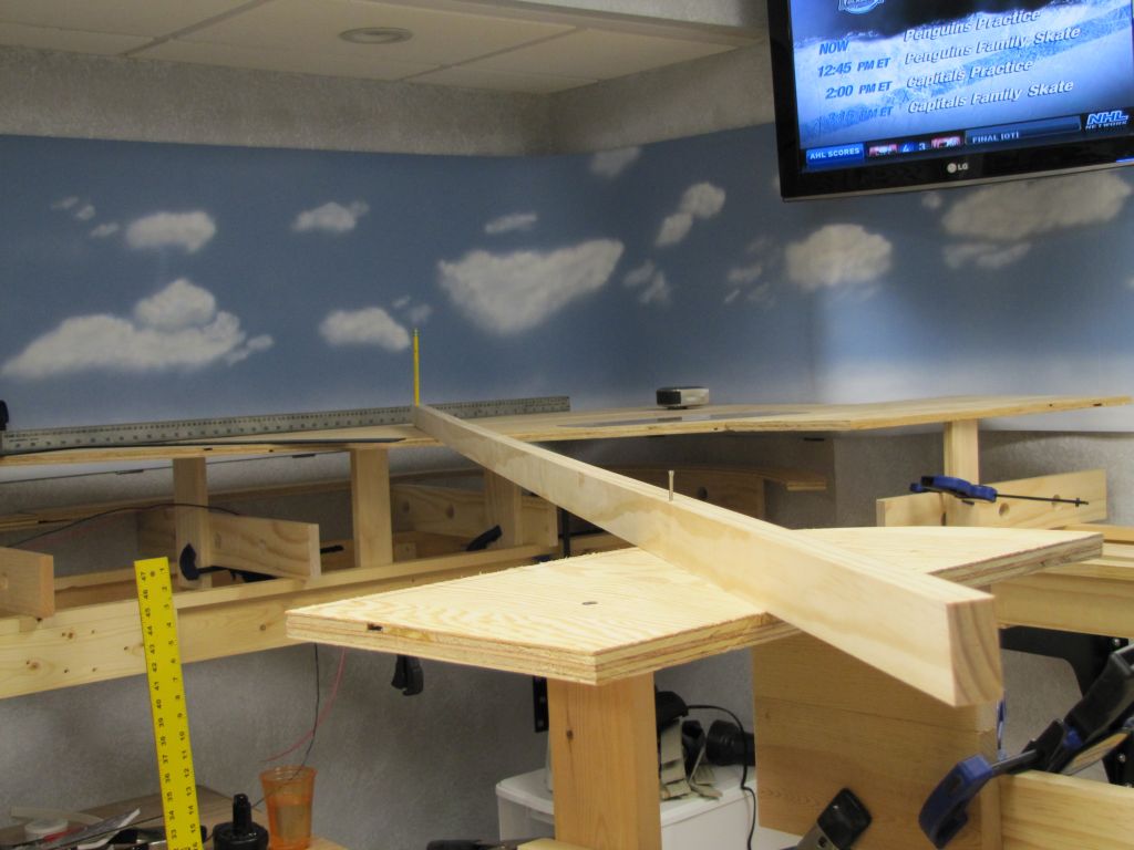

Meanwhile, upstairs, I've been working on some of the structures for the railroad - here's the coal mine head building under construction. This is a laser cut wood kit; structures will be both wood and plastic kits.
Next update should show the mainline complete!
Saturday, November 27, 2010
Weather - light clouds today, tomorrow, the next day...


(me) I'd like to buy some vinyl flooring remnants.
(them) Sure, do you have a style or pattern in mind?
(me) Doesn't matter.
(them) (funny looks)


Next, I'll be working on extending the track's main line around the entire layout.
Friday, October 15, 2010
Electrical wiring of first section

On the other hand, I do enjoy wiring, which includes LOTS of soldering, but light soldering - very different. Wiring is fun and rewarding, but it goes s-l-o-w-l-y! Wiring the track power is fairly straightforward - a 14ga bus runs all through the benchwork, and 18ga feeders run down from the track at about 3-foot intervals to the bus.

The turnouts in this area I want to operate together by selecting one of the 4 tracks, or a "route", and have the turnouts align as required for that route. This simplifies the control, but complicates the wiring a bit, requiring a series of diodes, which you see mounted on the vertical board at the top of the photo. If you're interested in a further explanation of how this works, CLICK HERE.
The sensors are near the end of each of the hidden tracks. This is a kit made for this purpose by Green Steam Products in California. It consists of the sensors, the (2) control circuit boards in the middle of the photo, and LEDs on the control panel.

Just to the upper right of the control knob is a single toggle and pushbutton pair, to control a single turnout in the area, and on the right a hole for a switch to turn on camera power - a camera will display what's going on under here on the TV.
Below is the back side of the control panel.

Saturday, August 28, 2010
First roadbed and track In place
I've chosen a commercial product called Homa-Bed (made from Homasote) for the roadbed. Where track will not be seen when the scenery is complete, I use Atlas code 100, while exposed track is Peco code 83. The "code" refers to the rail size, 100 being larger and more forgiving (good for hard-to-reach areas) and 83 being smaller and more to scale. The Peco brand is also much more realistic looking and of better construction.


Both the roadbed and track are glued in place with adhesive calk. Canned veggies make great weights!

Hidden turnouts (track switches) will be controlled by switch motors mounted above the plywood, while exposed turnouts have their machines mounted underneath. Turnouts aren't glued, but spiked down so they could be replaced if they fail. Here's a pair of turnouts and a switch motor:

The motor is mounted to the underside of the turnout; a rectangular hole is cut through the Homa-Bed and plywood. Here's one ready to mount in place:

...and placed:


The first sign of something "scenic" - the exposed track is airbrushed at this point, to color the crossties a dirty brown, and to lessen the "plastic" look. This is done now because as the track is "brought into service", it is prepped with a 3 step sanding (600, 1000 & 1200 grit), vacuumed, then burnished with a stainless steel washer, and finally the railhead is polished with Maas Metal Polish. I'm told that this burnishing and polishing process keeps the track cleaner than the more common "scrub it with an abraisive pad" method - it makes sense to me - no fine scratches for dirt to cling to - time will tell. Much more detail is yet to come on the track, but this painting needs to be done before sanding and polishing.

 Ooohhh, are those trains?!? Can a video be far behind?


Both the roadbed and track are glued in place with adhesive calk. Canned veggies make great weights!

Hidden turnouts (track switches) will be controlled by switch motors mounted above the plywood, while exposed turnouts have their machines mounted underneath. Turnouts aren't glued, but spiked down so they could be replaced if they fail. Here's a pair of turnouts and a switch motor:

The motor is mounted to the underside of the turnout; a rectangular hole is cut through the Homa-Bed and plywood. Here's one ready to mount in place:

...and placed:
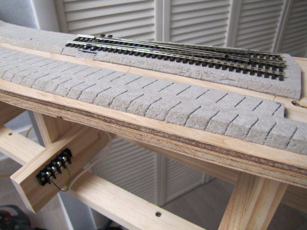
One of the spikes used to hold the turnouts in place:

I don't like soldering, because I've never mastered it! Despite this, most rail joints are soldered for strength. The track is fed from an electrical buss underneath; feeder wires are soldered to each track section.

The first sign of something "scenic" - the exposed track is airbrushed at this point, to color the crossties a dirty brown, and to lessen the "plastic" look. This is done now because as the track is "brought into service", it is prepped with a 3 step sanding (600, 1000 & 1200 grit), vacuumed, then burnished with a stainless steel washer, and finally the railhead is polished with Maas Metal Polish. I'm told that this burnishing and polishing process keeps the track cleaner than the more common "scrub it with an abraisive pad" method - it makes sense to me - no fine scratches for dirt to cling to - time will tell. Much more detail is yet to come on the track, but this painting needs to be done before sanding and polishing.


Friday, August 6, 2010
Plywood makes an appearance
Tired of looking at my dimensional pine? Here's some fir plywood for you!

This is the "subroadbed" for the tracks. (You can also see 2 of the 3 steel leg sets in these photos.) I've completed the plywood subroadbed in the isolated area above, which will eventually be a coal mining operation, the narrow section and lower level loop below:

...and a swing gate to connect them:


The lower level will not be seen in the finished model, there will be tracks and scenery above it. This lower level will serve as "hidden staging" - up to 4 trains will be staged here, ready to be called on to negotiate the hidden loop, cross the swing gate, then climb at a 2% grade (about 1.1 degrees) to the upper, exposed level. You can see that climb in the 1st photo - actually, the grade starts about 6" into the swing gate.
This alignment of subroadbed is the most critical of the entire railroad; I decided to get it out of the way first, and it took a lot of time to get it right. But, I'm happy to say, it's right!
Next up will be some roadbed & track on this area - and where there's track, there will be trains! Gotta test, right? Also coming soon, beginning the electrical work, and hanging the backdrops on the walls, while I can still reach them.

This is the "subroadbed" for the tracks. (You can also see 2 of the 3 steel leg sets in these photos.) I've completed the plywood subroadbed in the isolated area above, which will eventually be a coal mining operation, the narrow section and lower level loop below:

...and a swing gate to connect them:


The lower level will not be seen in the finished model, there will be tracks and scenery above it. This lower level will serve as "hidden staging" - up to 4 trains will be staged here, ready to be called on to negotiate the hidden loop, cross the swing gate, then climb at a 2% grade (about 1.1 degrees) to the upper, exposed level. You can see that climb in the 1st photo - actually, the grade starts about 6" into the swing gate.
This alignment of subroadbed is the most critical of the entire railroad; I decided to get it out of the way first, and it took a lot of time to get it right. But, I'm happy to say, it's right!
Next up will be some roadbed & track on this area - and where there's track, there will be trains! Gotta test, right? Also coming soon, beginning the electrical work, and hanging the backdrops on the walls, while I can still reach them.
Subscribe to:
Posts (Atom)