Sunday, December 11, 2011

Coal mining area and lift gate

Yeah, it's been slow going.  I have been working on a few projects, one being the coal mining / sorting / loading area.  The photo below shows the trackwork being "dry fit" before final mounting, and the partially completed coal tipple straddling the tracks to check the spacing.
Coal trains arriving here need the ability to either pull in locomotive first, or back in caboose first.  Either way, the loco or the caboose (with help from a switching engine) need to uncouple from the train, and then do a "run-around" maneuver to get back out while the coal hoppers are being loaded.

A little further up the line, the other project I've been working on has been a royal pain.  If you remember my previous railroad, you may recall the lift gate running past the sliding door in the basement, and that I had to rebuild that gate to get it right.  Well, what was once a swing gate on this railroad, at the room entry, has been rebuilt to be a lift-out section.  The swinging gate didn't provide a wide enough access to the room - just poor planning on my part.
Above, looking across the upper level of the lift-out toward the coal mining area;  below, looking across from the opposite direction.  Track and roadbed are yet to be replaced.

Saturday, October 15, 2011

Computers and the model railroad

There's a computer on my railroad!  Not what you may think of, but a computer none the less.  It's like one of the computers in your car, an electronic "magic box" that contains a processor, memory and some sort of operating software or firmware, so it meets the criteria to be a computer.

There it is, lurking under the locomotive above like a troll under a bridge.  It's a Digitrax DCS-100 DCC controller, the brain behind how my trains are operated.  I mention DCC control in the "About" page on this blog.  Now that I have the ability to run trains, it's time I do some basic programming of the individual decoders in each locomotive, such as assigning them an address other than the default number they all come with (3).  Once this is done, I can dial up that address - the one-to-four digit number on the side of each locomotive - on a handheld throttle, and I'm then controlling that loco.

That's pretty easily done, but decoders have a host of features involving both how each loco performs and sounds, that usually need to be adjusted, so that each one behaves pretty much like the others.  Different model and decoder manufacturers have their own way of doing things, and it's nice to establish some in-house standards.  (Standards do exist for DCC decoders and systems, these having been established by the National Model Railroad Association (NMRA), but they don't cover everything).  This can get pretty complex and tedious, when trying to program using only the handheld throttle - the only equivalent to a keyboard, mouse and monitor that the Digitrax computer has.

Fortunately, there is another organization that has developed a freeware program and interface to simplify this task - 
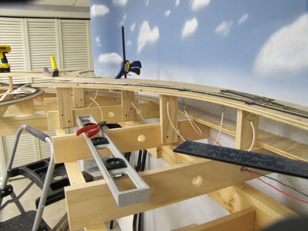
Decoder Pro by JMRI.  This software is run on a conventional PC (or Mac), and gives the user a nice graphical programming interface, with the loco usually resting on a specially wired programming track.  The loco in the first photo is on my temporary programming track;  I will eventually have one built into the layout, disguised as an abandoned siding.  It has to be insulated from the rest of the track.

A couple of Decoder Pro screenshots:

Computers, of course, can have other uses when actually attached to a model railroad.  The technology exists to completely or partially automate many functions, such as turnout routing (switching), signaling, and even full train control.  If I get into automated signalling before this thing is complete, I think that would be as far as I'd personally want to go.

When unattached, the internet, of course, has changed a lot about the hobby, as it has many aspects of our lives.  I can research most anything about the time period I'm modeling, and the now defunct railroads. I can shop for just about anything I need, new or used.  I can watch demos of how to do things on YouTube.  I enjoy reading a few model railroading forums on the web, and sometimes I'm able to contribute there, and help someone out.  That's pretty cool.

Last but not least, computers and the internet enable me to share all this with the world through this blog!

Saturday, August 27, 2011

Video part 2

And some faq's and comments on part 1:

Most questions can be answered by saying, "it's not finished".  Really, I'm not blowing you off!  But of course, there is no scenery yet, many solder joints in the wiring are not yet insulated, and the trains are still shiny and new looking - this will all change in time.

Is the locomotive we're following spinning up the grade?  Is this the longest train that particular loco can pull?  Yes, and right now, yes.  The grade in part 1 is the steepest on the layout, though it is not excessive.  I will be applying a traction compound to the drive wheels of all of the locos, and they will both not spin, and be able to pull more cars, up this grade.  The traction compound, by the way, is called Bull Frog Snot.

Yes, all of the sound in the videos, with the exception of my narration, is coming from each locomotive.

No, there is no smoke or steam.  At least one manufacturer, MTH, offers smoke on their locos - but that tends to gum things up eventually - what goes up, must come down.  And if you know me, you know that I smoke - but not in my home.  So if I don't smoke inside, I don't want my trains doing it, either!

Other than all that, I am pleased with this effort for a first video.  I know now that I need to use better lighting, and learned a lot in the process.  Hopefully, future videos will be a bit better, but I'm not trying to be a pro - it is what it is...

Here's part 2 - again, click on the YouTube logo, and watch it full screen there.  This one is 1080p HD - if you can get YouTube on your TV, it will look awwwwe-some!


Sunday, August 21, 2011

One year later

OK, 13 months, but who's counting?  To mark the occasion, my first video.

Best to click the YouTube logo, then watch it full screen there.  If your connection is fast enough, it's best resolution is 720p HD.


Saturday, August 20, 2011

Continuing fascia work

Continuing work on the fascia board, refining the contours at the top, and adding openings for access doors and control panels.

With DCC control, I have the option to control just about everything on the railroad from a hand-held device (transmitter).  Each device to be controlled this way would have to have a decoder (receiver), and an address.  These are called "stationary decoders".  I'm choosing to control just the locomotives themselves with the hand-held, so I'll call it a throttle.  Each locomotive contains a "mobile decoder" with a unique address - I set this to the one- to- four digit number printed on the loco's cab.  Control of switches for turnouts, lighting and other functions will be done from separate control panels around the fascia.

Below is the panel for lower staging, showing a schematic view of the track in that area, and appropriate controls to route trains in and out.  (I'm not thrilled with the graphics on the panel, and I'll be working on that - but you get the idea.)

Also seen both above and below are the throttle plug-in panels.  You can unplug a throttle from a panel - the loco will continue running on the last commands it had received - and re-plug at another location, to re-aquire control of the loco.  That way, you can walk around and be near the train as it moves around the layout, and also be near to the control panel associated with that area.

Below, the fascia is cut to just above the water level at what will be the fishing harbor scene.  The "water" will be just about 3/16" - 1/4" deep over the plywood base, but will appear much deeper (if I get it right!).  The resin fishing boat hulls are from kits I'll be building - they are called "waterline" hulls, since they are made to sit on the water's surface, as opposed to some other types of boat models that have a complete hull all the way to the bottom - which would look right when displayed on a stand.

Finally, a sneak peek at the (almost) finished fascia, as it will appear in my next posting - which will be a video tour of the layout!  I've completed the filming, and am now in post-production - lots to learn - video editing software is all new to me!  But interesting and fun, all part of the many different things the hobby can involve.


Thursday, July 14, 2011

Fascia board installed

Permanent wiring for the main line is complete, and trains are running!  I'm happy to say that test runs so far have uncovered only minor glitches in the trackwork, and these have been easily corrected.

Also up is the Masonite fascia board:

This fascia, unpainted right now, defines the edges of the railroad's "world".  Everything between the fascia and the backdrop sky will eventually be covered with scenery.  I trim the top of the Masonite to the contours of the terrain.  This may be adjusted as the scenery progresses.

The fascia will also provide a surface to mount control panels and connection jacks for handheld throttles - these will be cut in next.

Tuesday, July 5, 2011

Track is a model, too!

Mainline track prep is completed.  This is a (5) step process:  clean, paint, sand, burnish and protect.  Below is the code 100 Atlas track in an area that won't be seen, for comparison.  This track got a (4) step process - no paint:

The next shot is visible track - Peco code 83 - after painting - (2) colors are used:  Floquil "Railroad Tie Brown" is airbrushed over the entire track, then Floquil "Rail Brown" is applied to the sides of the rail:

Next, the top of the rail is block sanded with 800, then 1000, then 1200 grit paper.  This removes the paint from the railhead, which both looks correct, and is necessary for electrical contact, and smooths the surface.  The track is vacuumed between each grit, then cleaned with alcohol.

The railhead is then burnished with a stainless steel washer.  This removes any remaining imperfections in the surface, which would retain dirt and gunk.  After a final cleaning with alcohol, I apply a very light coating of a product called NO-OX ID, which will help to reduce oxidation, and improve electrical conductivity, without sacrificing traction.

It's hard to capture the gleam of the burnished railhead with the camera - here's a shot looking straight down, with flash:

The mainline is now ready-to-run - after I complete the permanent wiring.  Ballast - the rock between and around the cross-ties - and weathering with grease and oil colors, and weeds, will be done after the terrain is built.

Saturday, June 11, 2011

Mainline loop trackwork completed

Finally!  I had a friend ask if my railroad workers were on strike!  Picking up where the last update left off - as always, click the photos for a larger view -

Above, looking from the viaduct, the upper track crosses a double deck girder bridge, which was built from two single bridge kits, and along the "TV" wall, while the lower track emerges under the bridge, and winds lazily toward what will be a small fishing harbor area.  This track is climbing a grade beginning just as it appears from under the bridge.

Beyond that turn, the upper track begins descending, and crosses a wooden trestle bridge.  This bridge was stick-built from scale lumber, using plans from a magazine.  It had to be finished to a point to be put in place, but I'm not giving away any closeup photos until it's complete!  The lower track continues to climb and turn, and as seen in the overview shot below, ultimately joins up with the upper track, to complete the loop.

So, now comes some tedious work with wiring, cross tie and rail painting, and cleaning and polishing the rail of the mainline loop.  When that is completed, continuous test running can begin, and any trackwork or electrical "kinks" that may be found will be worked out.

Monday, January 17, 2011

More trackwork, and a mockup

Trackwork (plywood, roadbed and track) has now reached the south wall of the room, under the TV.  All of the track power wiring (red & black) is in place;  the dangling telephone cables you see in some photos are for the turnout motors.  One of the scenes I'll be modeling, a curved stone viaduct crossing a river and valley, is shown here as a mockup  This helps me visualize the scene in 3D, and give me a better feel for how things are going to look.  The bridge at the right, by the way, is not the correct bridge that will go there - it's just a stand-in.
The double-tracked main line is shown above leaving the swing gate, while a wye branches off to the left.  The "tail" of the wye will serve a TOFC (Trailer On Flat Car) operation - this is the forerunner of modern single and double-stacked container trains seen today.
A little further along, looking in the same direction, the main is on the left, and approaches the viaduct in the distance.  Branching off here, coming at you to the right, is a spur track which will serve the coal mine.

A couple of photos showing construction in this area.  The last shows a wooden trammel I used to swing the radius lines at the viaduct area - the inner track here has a whopping 80" radius.  This is typically how I lay out the track centerlines and the cut lines on the plywood;  I have plastic templates for the more common radius track on the railroad.  The NHL Network has their "Winter Classic" hockey coverage schedule on the TV screen!

Meanwhile, upstairs, I've been working on some of the structures for the railroad - here's the coal mine head building under construction.  This is a laser cut wood kit;  structures will be both wood and plastic kits.

Next update should show the mainline complete!